Introduction to P25
P25 Network Architecture
P25 Site Equipment
The site equipment in a P25 radio site is very similar to the site equipment at an analog radio site. One of the goals of P25 was to be able to remove an analog channel, and install a P25 channel in its place on the same frequency. Although a P25 network can be a conventional network or a trunked network, in each case the site equipment is very similar. This section will provide a general overview of a P25 radio site and highlight some of the key points.
A radio site will have an antenna system. This is the same for a P25 or for an analog radio site. A tower or mast will have either omnidirectional or directional antennas, depending on the type of coverage footprint needed. Combining and filtering equipment can allow multiple channels to connect to the same antenna, and, like analog repeaters, there is a range of power supply options available for P25 radio equipment.
The site may run on AC mains power or be DC powered, often 12, 24 or 48 volts. In many cases, there will be backup power, such as batteries or generators installed at the radio site.
The P25 repeater equipment is typically made up of the following:
- a power supply unit to match the power supply available at the site;
- a power amplifier of a suitable output power, such as 50W or 100W;
- a receiver and transmitter – sometimes these are in the same physical module;
- a network interface.
The network interface may be integrated into the repeater or a separate module. It is typically integrated into the repeater, but it may be a separate module, and often there is an analog audio interface available.
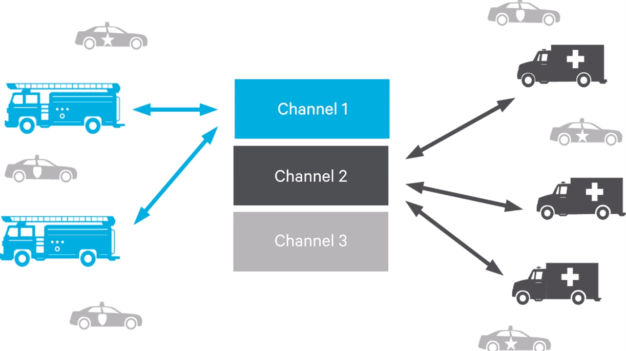
In a conventional system, all the repeaters are used for voice or data calls, or traffic calls for the end users. The mobile and portable radios are manually switched to the correct channel, and the users communicate by pressing the Push-to-Talk button.
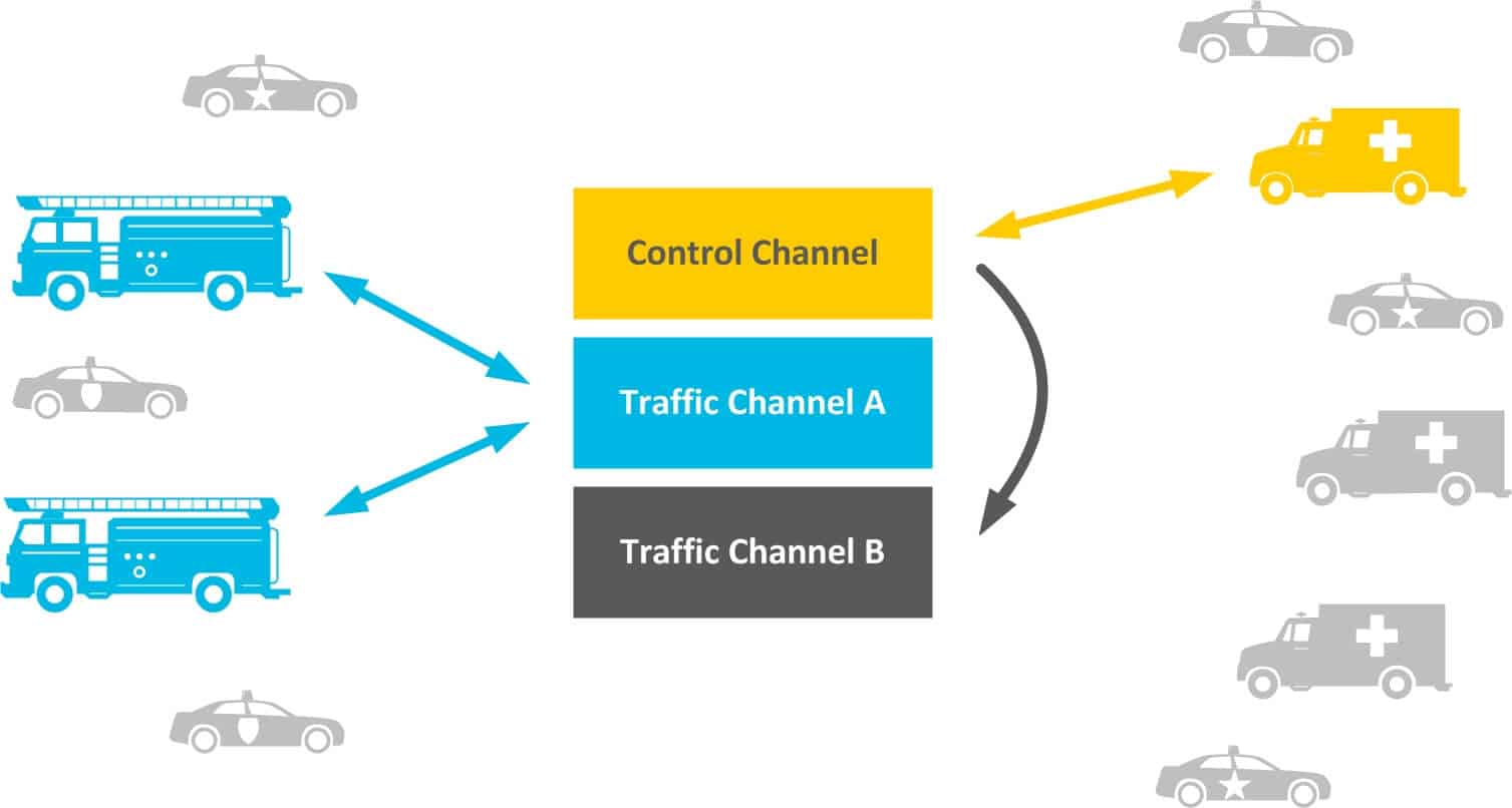
In a trunked system, there is a pool of repeaters available for voice and data calls. These are called the traffic channels, and in addition, there is one repeater that acts as a control channel.
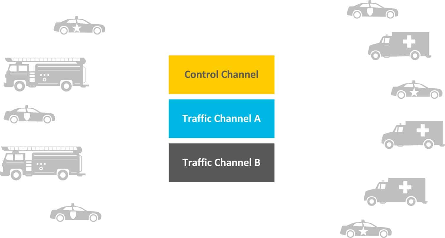
The control channel does not carry voice or data calls. Instead, it is used by the trunking system to communicate with the mobile and portable radios, allowing them to request and be allocated a traffic channel from the pool of available repeaters.
A P25 site is typically IP-connected and may carry voice, data, and remote management. An IP switch connects all the repeater and control equipment together, forming a local area network at the site; there may also be a router that connects to the linking equipment to other sites.
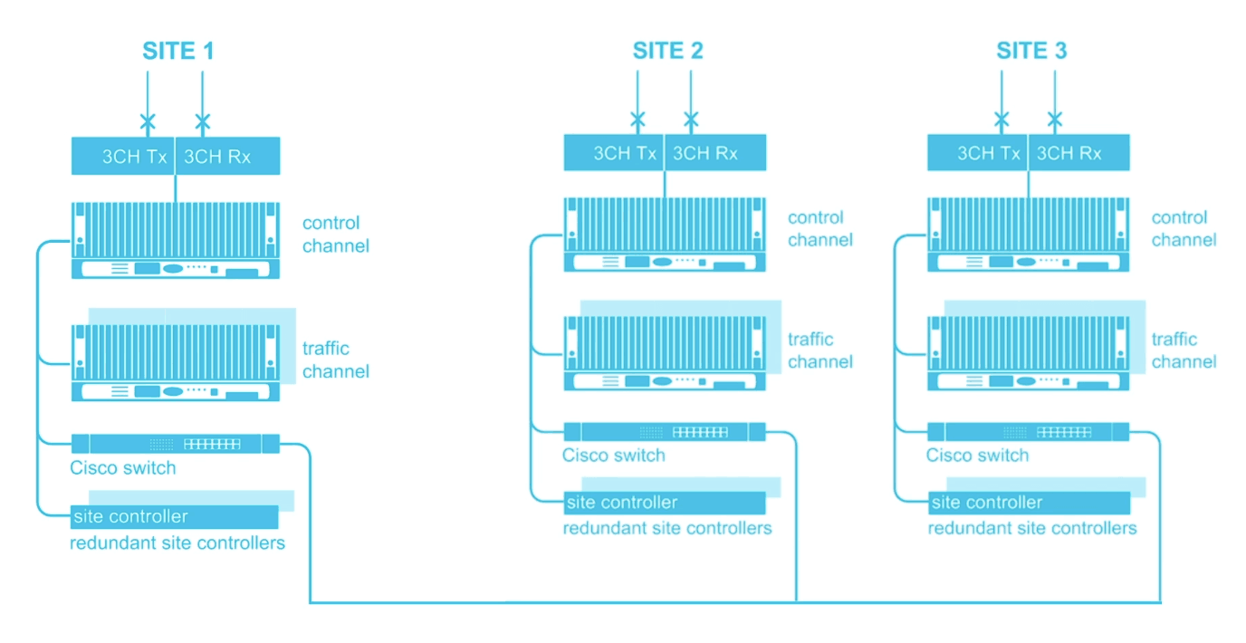
In addition to the networking equipment, there is likely to be linking. This may be part of the radio network, or provided by a third party. Typical links are microwave or fiber. However, other emerging technologies such as MiMOMax or legacy equipment, such as PDH systems may be used.
In a trunked system, there is likely to be control equipment onsite. This may be a server running software, or a dedicated device that controls the repeaters. In other cases, this control equipment may be located off-site, and control the repeaters over the IP link.
A conventional network may not have any control equipment at a site, and may simply have the repeaters. However, a large conventional system that connects multiple sites together may still have control equipment to vote on the best signal being received from the multiple sites. Often this function is now built into the repeaters themselves, rather than being external equipment.
Course lessons
Register for Radio Academy
Register for the Radio Academy to:
- keep track of your course progress,
- download the course study guide,
- ask and answer questions in the forums,
- earn a certificate at the end of the course.