Introduction to DMR
DMR Network Architecture
Network Overview
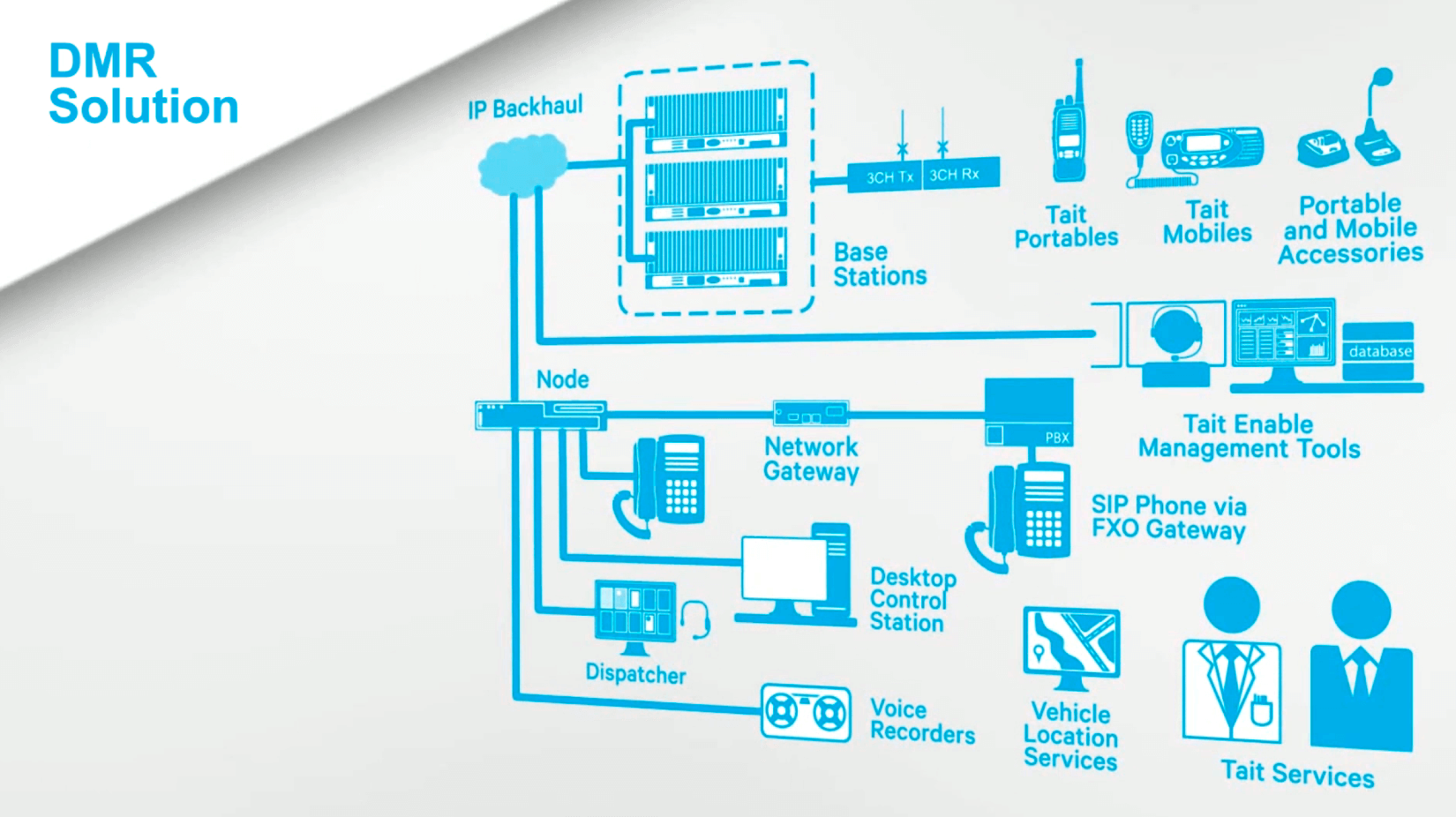
A typical DMR network consists of one or more node controllers and a number of sites. Each site is made up of several base stations connected by an IP backbone that can be either a switched local area network (LAN), or a routed wide area network (WAN) through the use of routers and bearers.

The DMR network design is scalable from a single site to a large, wide area network with multiple node controllers controlling hundreds of sites. Open standard protocols are implemented to provide gateways to non-DMR base stations/repeaters and digital or analog dispatch console equipment.
Radio networks of differing manufacturers and technologies can also be connected together through DMR networks, creating a simple migration path or large-scale communication systems
There are some key elements of the network, we’ll look at them in a little more detail later, but here are the basics:
- A Linking infrastructure, or the IP backbone, interconnects the various elements of the DMR network.
- DMR site equipment, such as base stations or repeaters, provides the RF path to and from the mobile and portable radios for the voice or data communications.
- DMR nodes control the call setup, generate and store call records and raise alarms.
- Network gateways provide an audio interface to equipment and systems outside the DMR system.
- Telephone gateways support direct communications between radios and external telephones through the PSTN/PABX.
- DMR mobile and portable subscriber units are used to communicate between radio users and other network-connected devices.
A full DMR solution will, as indicated in this diagram, integrate a wide variety of third-party elements like voice recorders, dispatchers and applications.
Course lessons
Register for Radio Academy
Register for the Radio Academy to:
- keep track of your course progress,
- download the course study guide,
- ask and answer questions in the forums,
- earn a certificate at the end of the course.
