Introduction to P25
Channel Operation and Configuration
Channel Configuration and Numbering
This topic will cover three different elements of a P25 network:
- how units and groups are numbered in a P25 radio system,
- how a P25 trunked network is identified,
- how radio channels are addressed on a trunked system.
1. Unit and group numbering
Every subscriber unit in a P25 radio system has a Unit ID.
The Unit ID is a 24bit address, a hexadecimal that is from 0 to FFFFFF, or in decimal that contains 16,777,216 individual ID’s. Some of these ID’s are reserved for special functions, such as identifying the trunk network, and typically individual radios are numbered in the range from Unit 1 to Unit 9,999,999.
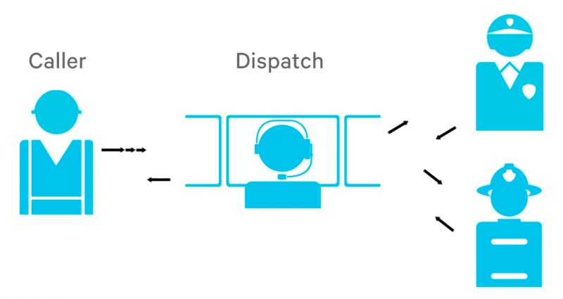
This Unit ID is transmitted when a call is made and can be used by the receiving radio to show the Caller ID of the person talking.
An individual call or unit to unit call to another radio is possible as well, by transmitting that radio’s Unit ID as a destination address.
This large pool of addresses allows blocks of ID’s to be allocated to individual agencies or groups. For example, if five digit ID’s are used, the first digit might identify the team or group that the radio is issued to. The second digit might identify whether it’s a portable or mobile radio, then the last three digits could be used to uniquely identify that individual or vehicle in the fleet.
P25 allows for group calls to be made to a team of people. This is achieved by addressing the call to a particular talk group, rather than an individual radio.
Talk group numbers have a 16bit number. In hexadecimal, that is from 0 to FFFF and contains 65,535 group addresses. The address FFFF is a special address that means an all-call to all units in the system.
Trunk systems also allow announcement groups to be defined. This is a group of other groups. In addition to this all-call address to everybody on the network, trunk systems allow announcement groups to be defined.
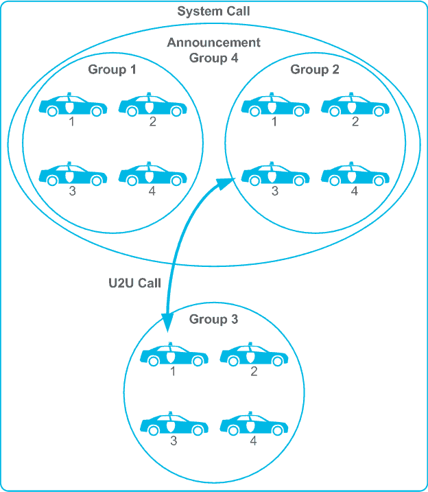
An announcement group is a group made up of a number of smaller groups. So one call could be made as an announcement to multiple teams. Unlike some other radio standards, the P25 unit and group number ranges are independent. You can have both a Unit one and a Group one.
Now that we’ve looked at unit and group number ranges, we’ll look at system numbering.
2. Identifying a P25 Network
It is possible for more than one organization to install a P25 trunk system in the same area. Each system could have many sites that would still be a unique radio frequency sub-systems (RFFS).
A wide area network may be created by joining smaller RFFSs together. An individual radio or subscriber unit may or may not be permitted to roam from one RFSS to another. Therefore, it is important that the radio can identify what system a particular site belongs to.
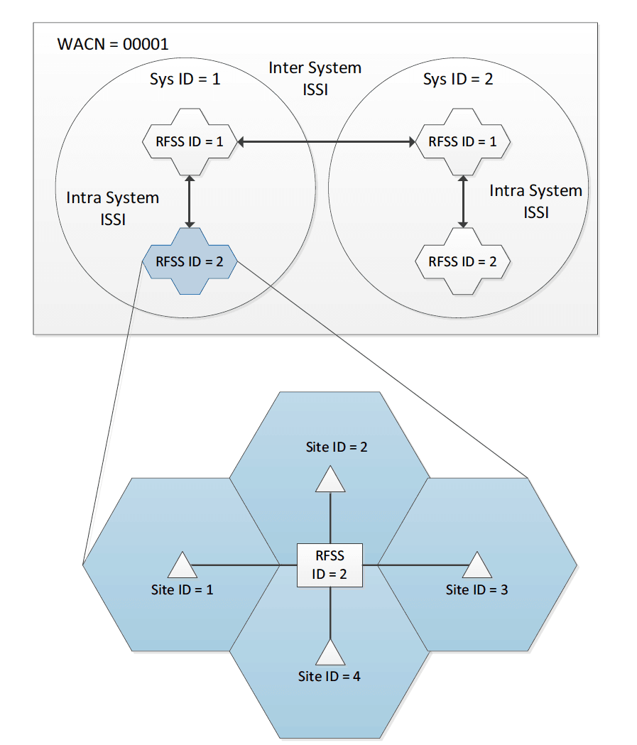
To allow this to occur, each site has a control channel that is constantly broadcasting messages that identify both the site and the system that site belongs to. A Wide Area Communications Network (WACN) address is a 20bit number from 1 to FFFFE in hexadecimal, which allows over 1 million unique networks to be defined.
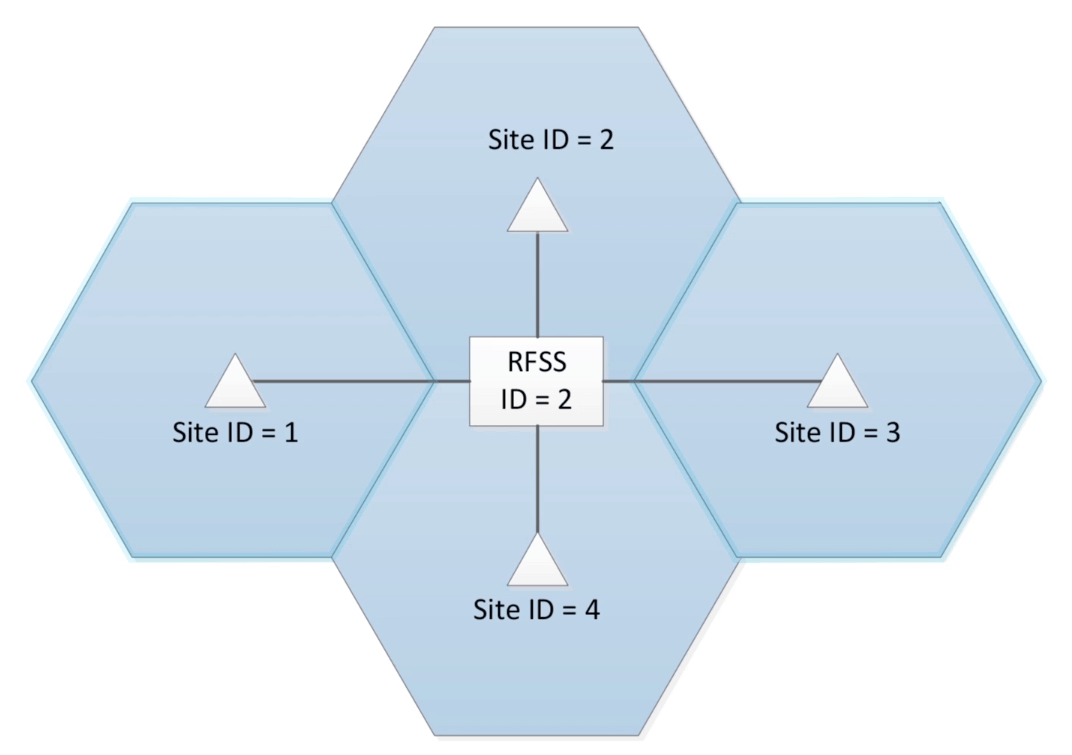
There is then a system identity or a 12bit number that can identify over 4,000 systems per wide area communication network. The Telecommunications Industry Association (TIA) have a guideline document that describes how WACN and System ID’s could be allocated, to prevent two agencies having a system with the same address. In addition to the WACN and System ID, a radio site will also broadcast its radio frequency sub-system ID, or RFSS Identity. This is an 8bit number from 1 to 254 and the individual site address which is also an 8bit number.
The broadcasting of these system and network IDs allow a radio to roam around the network and always identify the best site from which to make calls. It also allows the system administrator to restrict units or groups to coverage from specific sites. This can be very important when planning capacity for the network and how many channels will be needed in which area. In addition to the system numbering, there is a Network Access Code (NAC code). A NAC Code is used in both trunked and conventional radio systems.
The NAC is a 12bit number in the range 0 to FFF and contains 4,096 addresses. This is programmed into both the mobile and portable radios and into the repeater, and can be used as a means of selectively accessing the base station infrastructure, providing a function very much like subaudible tones used in analog systems. This can be important when there are a limited number of frequencies available and the same radio frequencies are reused at two sites.
In a Network design, this is acceptable, providing there is enough separation between the sites that the coverage does not overlap. However, because of terrain variation and the fact that mobile and portable radios move around. There’s still a risk that at some point a mobile or portable radio intending to talk on one repeater is picked up by the other repeater using the same frequency. If a different NAC code is programmed into each repeater, it will mean the correct repeater will rebroadcast the call and the other will reject the transmission.
3. Channel addressing in a trunked system
In a conventional radio system, mobile and portable radios are pre-programmed with the channels that they use. In a trunked network, a pool of channels is available at each site that the network can allocate for calls. The available channels can change over time, as the system grows and expands.
Rather than reprogram all the subscriber units each time a channel is added to the network, the mobile and portable radios are simply programmed with one or more channel plans, from which the frequency of all available and future channels can be calculated.
To do this, the radio spectrum is broken up into ranges or blocks of frequencies. Each block is given an ID that defines a set of continuous channels with common parameters. This is called a channel identifier or a frequency plan.
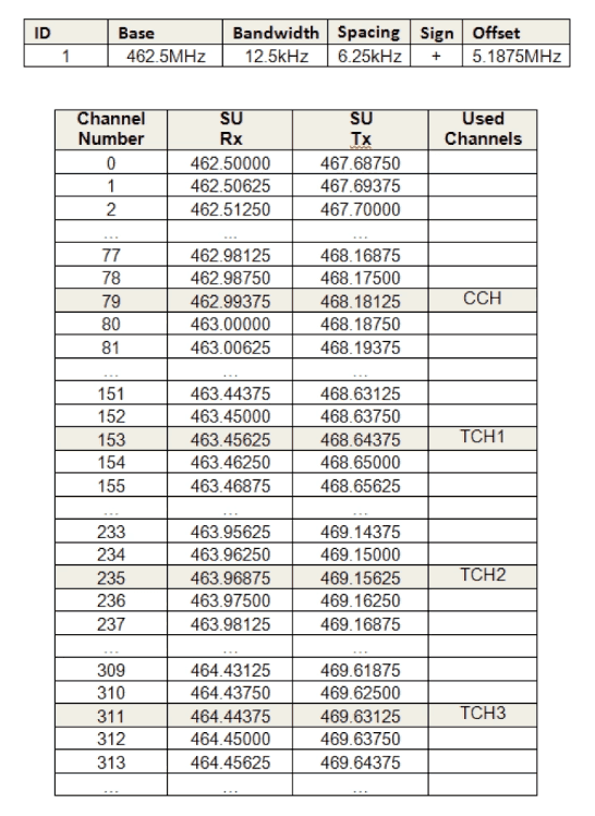
All the parameters in a frequency plan are named from the perspective of the subscriber unit, not the network. This means the same names can be used for the parameters, irrespective of whether they’re being programmed into a subscriber unit or an RFSS controller.
The parameters include an ID, which is a unique identifier for the frequency plan, the bandwidth, the channel, (normally for the P25 this is 12.5 kHz), then the transmit offset which is the size in mHz of the difference between the receiving transmit frequency.
The plan also includes the channel spacing, which is the spacing in kHz between one channel and the next and a base frequency, which is the frequency of channel zero in the channel plan. On a trunked network, when a subscriber unit requests a call, the system responds with the channel plan and channel number to use for that call. The subscriber unit then calculates the receive and transmit frequencies to use, based on the channel plan.
Course lessons
Register for Radio Academy
Register for the Radio Academy to:
- keep track of your course progress,
- download the course study guide,
- ask and answer questions in the forums,
- earn a certificate at the end of the course.