Introduction to P25
Channel Operation and Configuration
Channel Operation
This topic is going to compare the operation of a conventional FM channel to a P25 conventional channel, then review the difference between a call on a conventional network to a call on a trunked network.
Analog FM channels and calls
On an analog FM channel, when the PTT is pressed, the microphone converts the speech into an analog electrical signal. It is amplified and filtered to pass only frequencies on a range 300Hz to 3kHz. This audio band contains all the frequencies required to understand human voice. The audio may also be pre-emphasized, which allows for some of the noise picked up during transmission to be reduced in the receiver.
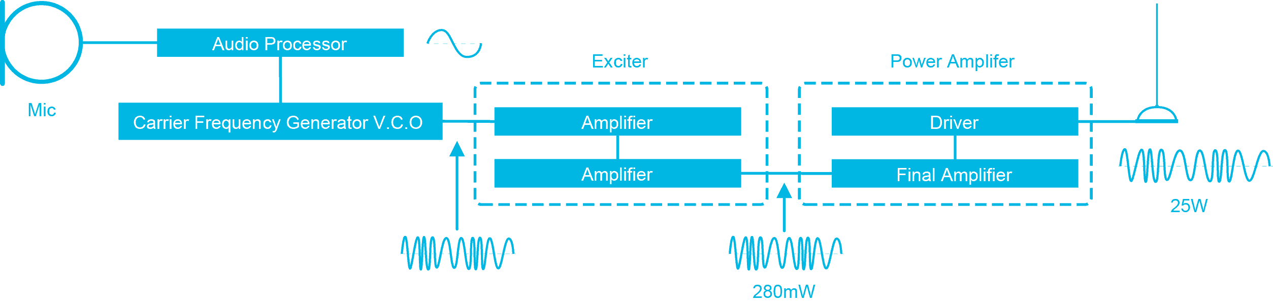
Analog signaling, if used, is then added. This signaling may be in the form of a sub-audible tone used to control access to a repeater, or a tone or data burst added at the start or the end of a call to identify the caller or the intended recipient of the call. The audio and any signaling is then encoded onto an RF carrier. The encoding device is a voltage controlled oscillator (VCO) and produces frequency modulation or FM.
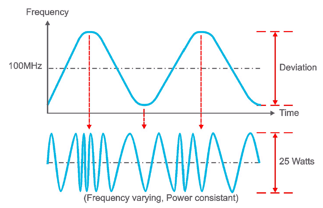
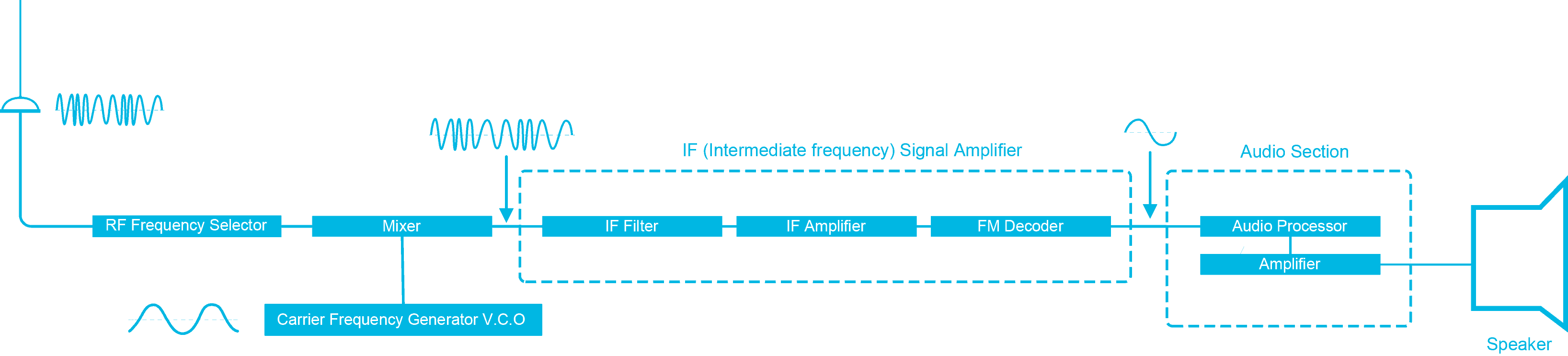
In FM, the carrier deviates in relationship to the amplitude of the audio. The frequency modulated signal is then amplified and transmitted. In the FM receiver, the FM signal that was transmitted, plus any noise picked up along the way is converted back into analog audio.
De-emphasis can reduce some of the noise picked up during transmission, but it cannot remove it altogether. This audio, plus any of the noise that was picked up during transmission, will be output by the speaker.
P25 Channels and Calls
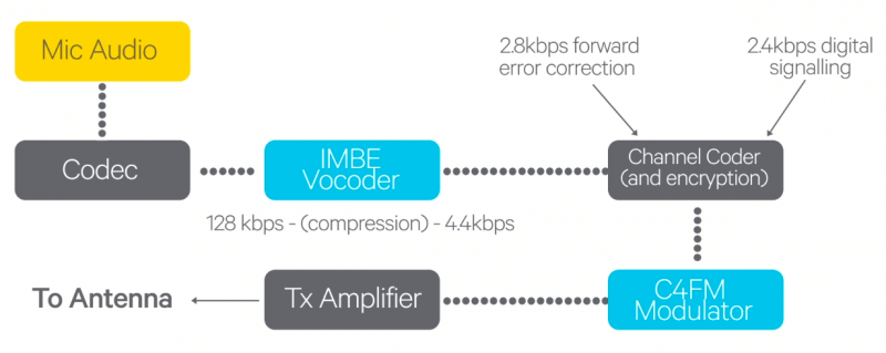
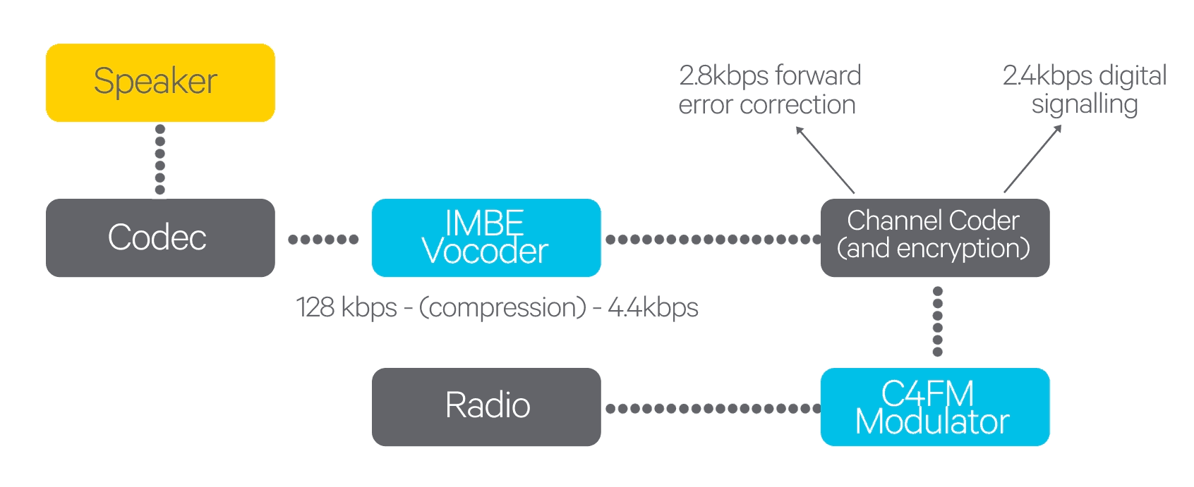
On a P25 channel, when the PTT is pressed, the P25 Common Air Interface (CAI) works as follows – the microphone first converts the speech into an analog electrical signal. A device called a Codec samples that signal and converts it into 128 kb per second data stream of digital information representing the voice.
A device called a voice coder or Vocoder then processes that data and uses a technique called Improved Multi Band Excitation (IMBE). This removes much of the background noise by encoding only the characteristics in the signal that represent human voice. It also compresses the voice into a data rate of 4.4 kb per second.
Then to protect the voice signal from errors caused by failing or interference during transmission, 2.8 kb per second of forward error correction is added to the voice. Signaling information used to control access to the repeater, and identify the caller or intended recipient, is interwoven with the voice signal, adding a further 2.4 kb per second to the data stream.
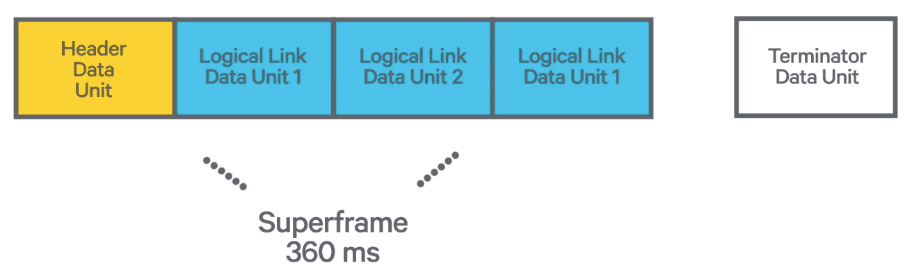
The output of the Vocoder may also be encrypted to protect the voice from unauthorized listening. The signaling, voice and error correction is then formatted into P25 speech frames. A transmission starts with a header data unit, identifying the destination of the call and if encryption was used or not.
It then continues with a series of logical link data units (LDUs), that carry the digital speech. The LDUs also repeat the signaling information and the synchronization sequence, so radios can join the call late, or reenter if they drop out due to bad RF coverage and then come back into the call. The call ends with a terminator data unit, indicating that the PTT’s been released, and this is the end of the call.
In the P25 radio, a modem modulates the carrier with this digital data. In phase one of P25, this is done using a modulation scheme known as C4FM. The signal is then amplified and sent to the antenna to be transmitted.
When receiving a P25 signal, the reverse of the transmit procedure takes place. The radio demodulates the signal, and corrects any errors and extracts the signaling. The Vocoder and the Codec then reconstruct the original analog voice signal from the digital data. Because of the error correction and the fact that the transmission was digital, any noise picked up during the transmission does not appear in the reconstructed analog voice. This audio is then output via a speaker.
The major advantage of P25 is the ability to reduce the amount of noise heard in a transmission, and also to encrypt a call without any loss of audio quality. Both of the examples above looked at how the transmission that begins when the user presses the Push To Talk, or PTT, and ends when he or she releases the PTT, occurs on a conventional channel.
On a trunked system, there are a number of additional steps:
First, there is hunting and registration, which happens when the radio’s first turned on. The radio is then turned on and automatically identifies the closest site and requests permission to use the network. Next is affiliation, where the radio automatically requests permission to use a particular group. All of this takes place on a dedicated channel called the control channel.
Once the radio is registered and affiliated, it will indicate that it has service and can be used to make calls. When the PTT is pressed on a trunked system, the radio first sends a message on the control channel, requesting permission to make a call. The trunked network then responds on the control channel with the ID number of a traffic channel to use for the voice call.
This information is received by the calling radio, and by all of the radios in the group that were called. All the radios then automatically tune to the traffic channel, and the call can take place.
This call set up all takes place in less than one second. At this point, all the radios are on the traffic channel and the voice is transmitted just like on a conventional radio channel. When the PTT is released, the channel may be reserved for a few seconds to allow a reply to the transmission, at which point the call ends and all of the radios return to the control channel, ready for the next call.
Course lessons
Register for Radio Academy
Register for the Radio Academy to:
- keep track of your course progress,
- download the course study guide,
- ask and answer questions in the forums,
- earn a certificate at the end of the course.